Here is a little project I have been working on for the past few months. This project is essentially a Wiegand code generator and a range extender over IP. I gave it the nickname WEX (Wiegand EXtender). While eventually it could become a real commercial or open source product, right now it is mainly a tool I couldn’t do without.
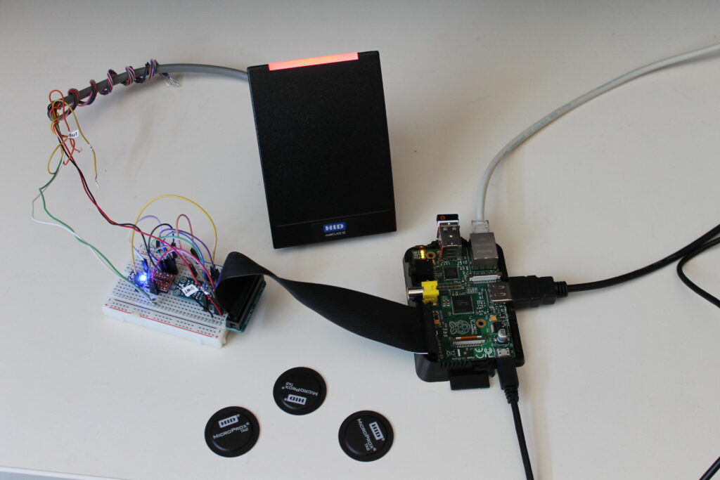
The motivation:
Few month ago, while I was working on a .net C# web service application, I realize that I had no real way of testing this new application. My application was creating a bridge between the Kantech Hattrix access control system and a customer HR system. Of course I could swipe a card in front a access control reader a couple of time to get some access granted and simulate how my software would behave (and I did of course), but since the customer was a large company with more than 1000 swipes per hour, I knew I had to come up with something better to emulate this scenario.
The challenge:
My initial goal was to create a tool that could attached itself to the card reader port of an access controller (in this case a Kantech KT-300) and generate at regular intervals, a card swipe (wiegand data pulses). The solution had to be controlled remotely over the network (I’m lazy, I did not want to walk to the generator each time I wanted to start a test). Finally, it had to be cheap.
Everybody loves PI:
Since I’ve been playing for a couple of month with the Raspberry PI, I decided this project would be a perfect candidate for this small and cheap single board computer.
The PI has GPIOs pins, runs Linux (Raspbian, a Raspberry PI Linux flavour) and is amazingly user friendly. Like many other people I bought a Raspberry PI out of curiosity, without any real intendend purpose. I got one now.
Hardware requirements:
My first step was to get a wiegand interface on the PI. As Wikipedia is rightfully putting it:
The Wiegand interface uses three wires, one of which is a common ground and two of which are data transmission wires usually called DATA0 and DATA1, alternately labeled “D0” and “D1” or “Data Low” and “Data High”. When no data is being sent, both DATA0 and DATA1 are pulled up to the “high” voltage level — usually +5 VDC. When a 0 is sent the DATA0 wire is pulled to a low voltage while the DATA1 wire stays at a high voltage. When a 1 is sent the DATA1 wire is pulled to a low voltage while DATA0 stays at a high voltage
This translate to the following graphic in the logic analyser when you present a card in front of the HID card reader.
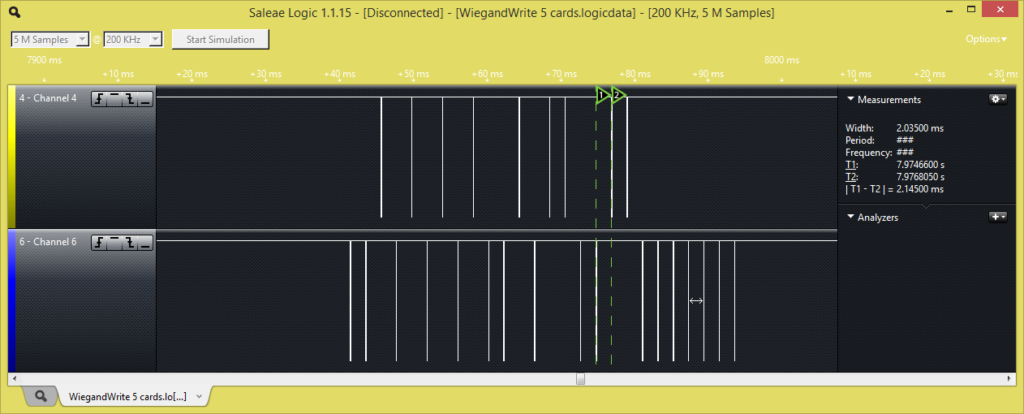
The screen is split in half where the upper part is DATA0 (the green wire) and the bottom part is DATA1 (the white wire). The vertical line are drop in voltage for about 40 μs (microseconds). The firmware will need to detect this voltage dropped and transcode this information in binary format.
The simple circuit:
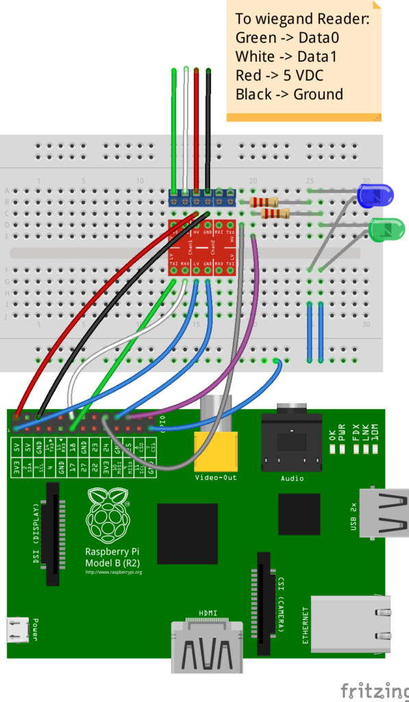
The following very simple circuit was only created to protect the 3.3v Raspberry PI GPIO pins from the 5v output of the Wiegand reader. In order to achieve this I picked up the Bi-Directionnal Logic Level Converter from Sparkfun. But the 4-channel Bi-directional Logic Level Converter board from Adafruit would have done the trick too. I added a couple of leds just to get a status update of the different operations.
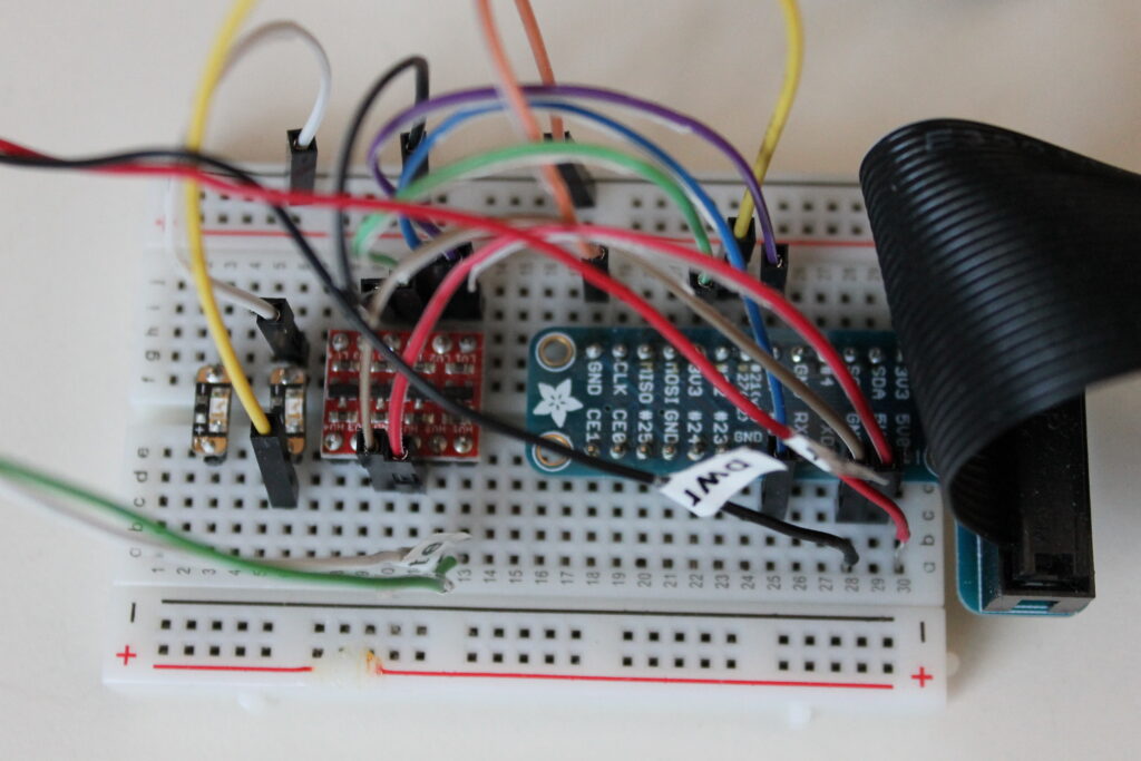
In this setup, the wiegand card reader (connected to pin 17 and 18) is taking its power from the 5v output of the PI.
Here is a diagram of the connections. The LEDs are simply used for status updates (card generation, card read, TCP/IP connection status, …).
The firmware development:
Many developers out there had a hard time to get the PI to read Wiegand data .The main cause of their failure was most likely the fact they tried to use an interpreted language (such as Python) to read the wiegand pulses, microseconds apart. This kind of language was not really intended for this type of job.
This is why I decided to use a development language such as C/C++ and a compiled binary. I used a cross compiler on Linux Ubuntu with the Eclipse IDE. The program is compiles using the arm-bcm2708 GCC cross compiler tool-chain (a good guide for this is found here). While I could accessed directly the GPIOs, I still decided to use the WiringPi library. Gordon (the creator of the lib) did a great job at simplifying the process and use a syntax similar to Arduino.
The WEX operations:
The operation of the program is separated in 3 modes:
- Wiegand signal read from the GPIOs
- Wiegand signal write to the GPIOs
- Wiegand code generator
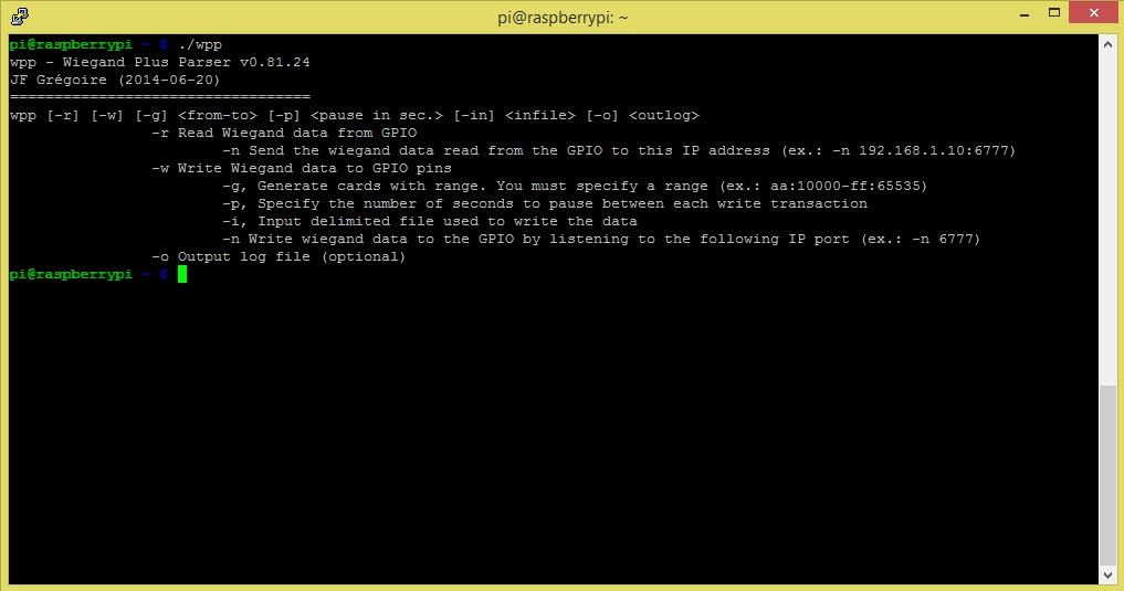
Here is a screenshot of the program command line (connected by ssh to the PI):
Wiegand signal read mode:
The read mode is very useful to read the identity of a card, log transactions to a file or to send Wiegand signal over the network. Here is a few examples:
./wpp -r -o myLog.csv
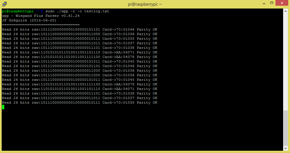
The previous command will start wex in read mode and display on screen every wiegand read it gets (typically coming from a wiegand reader attached to the raspberry PI). The transactions are also logged to a comma delimited file under the name of myLog.csv. Please note this command need to be preceed by “sudo” to grant supervisory rights since we are accessing the GPIOs.
You will notice that on each read sequence, the Wex software count the number of bits received, display the raw representation in binary, display the interpretation (site:ID) and confirm the validity of the checksum.
The following is similar to the previous command, but this time we are sending the Wiegand signal we read from the GPIOs to a remote network IP address.
./wpp -r -n 192.168.1.67:6777 -o myLog.csv
The data is sent through an encrypted TCP/IP connection. At this time, the communication is unidirectional. It is only from the reader to the remote writer.
As you might guess the remote recipient will be a WEX software in the wiegand signal write mode (see next section).
Wiegand signal write mode:
The wiegand signal write mode is useful to relay the wiegand data from a remote reader over the network (running wex in a Raspberry PI, connected to a card reader). The wex in write mode would typically be attached to a access controller. Here is an example
./wpp -w -n 6777 -o myServerLog.csv
In this mode the wex program will act as a server and receive wiegand data from any wex reader by listening to the network port 6777. So with two networked Raspberry PI, one attached to the card reader and one attached to an access controller we just created a wiegand range extender. In effect, the card reader could be in Montreal and the access controller in Taiwan. The distance does not really matter. Alternatively, you could also connect the Raspberry Pi over the network with Wifi dongles and you got yourself a wifi reader.
Wiegand signal generator mode:
While the previous description of wiegand data transmission over the network is an interesting concept, it is actually a side effect of the main purpose why I developed the code in the first place. That is, to generate wiegand data.
In this mode, the Wex program generate at fix interval a wiegand data pulse. Here is an example:
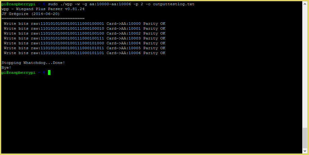
./wpp -w -g AA:10000-AA:10006 -p 2 -0 outputtestlog.txt
The previous command will output 7 wiegand data pulse through GPIO 17 and 18 with a pause of 2 seconds between each transmission. It will then terminate by itself. If you attached the PI to an access controller for example, it would simulate someone swapping 7 different cards.
Since I like to generate lots of traffic, I usually specify larger range like (AA:00001- AA:65535). This will keep the access control equipment busy for a while.
What’s next:
Of course, this is a modest little software that I find useful in my specific development context. It shows however some of the great potential of this little 35$ micro-controller.
Here is some of the features I am currently working on:
- Real-time watchdog
- Network encryption
- Led and buzzer feedback (card reader feedback)
- Remote relay operations (remote door unlock)

Hey there! I know this is somewhat offf topic but I was wondering if you knew where I could locate a captcha
plugin for my comment form? I’m using thee
same blog plafform as yours and I’m having difficulty
finding one? Thanks a lot!
No sorry. But if you find one I would be interested as well
You actually mae it seem so easy with your presentation but I find this matter to be actually something that I think I would never understand.
It seems too complex annd extremely broad for me. I amm looking forward for your next post, I’ll try to
get the hang of it!
Greetings! I’ve been following your website for a while now and finally goot the courage to go ahead and give you a shout ouut from Atascocita Tx!
Just wanted to tell you keep up the excellent job!
I do not even know how I ended up here, but I thought this post was great.
I do not know who you are but certainly you’re going to a famous blogger if you are not already 😉 Cheers!
Hi Gregzy,
Do you a the tool for download ? i testing sobre reader and controllers and this tool would be great to read and write to Wiegand interfaces.
Antonio
Hi,
Sure, let me compile a fresh version and it should be up in a coupe of days. I’ll send it to you.
Gregzy
Hi,
thank you for the post.
during write, the reader is forcing the line HIGH and the PI is forcing it LOW.
Is this going to cause a problem for the reader?
What happens if you are forcing a write during someone swapping a card?
Hi,
Actually the Write mode is used when you connect the PI to an access controller (to simulate a reader or transfer swipe from a remote PI in Read mode). So you never get a conflit since you are either in read mode (and you are listening to a reader wiegand output) or write mode ( you are writing output wiegand signals).
You cannot do both at the same time.
However, the next version I’m workingon intergrates the Buzzer and led wire of the reader. A typical access controller would read from the Wiegand and write output signal through the led and buzzer wires. This makes Wiegand sort of bi-directionnal. This is how the access controller signal the user he got access granted or denied. The LED and buzzer would sound and flash in a specific sequence depending on the Wiegand card that was read.
Gregzy
Hi
what if I want to connect the arduino mega to the lines connecting the reader to the switch. assuming 2 output pins are connected directly to the D1 and D0.
every day at 8:00 am and on 5:00 pm the mega will send a sequence similar to the ones produced by the reader whenever a my finger print is applied.
assuming others are using the reader at 9:00 am and at 6:00pm.
can I drive D1 and D0 low to simulate 1s and 0s?
should I use a 10k pull up resistor?
Yes, I don’t see why not. You should be able to emulate a reader by sending 1s and 0s. However, make sure that you also connect the ground. By experience we always connect at least 3 wire (D0, D1 and ground) to operate properly. Otherwise you might get erratic behaviours. In my case, my reader takes its power from the Raspberry PI so I have 4 connections (D0, D1, 5V, Ground).
As for the 10K pull up resistor, I never tried it. In theory it should work.
Hi,
do you know how the output of the reader on D1 and D0 is built? is it similar to the RS485?
a schematics or a link to the last stage of D1 Do hardware is appreciated.
with that we can be sure.
regards
Hi,
No, wiegand is a bit particular compare to RS232/RS485. In RS232 for instance you have one wire for transmiting and one for receiving. You have additionnal wires for handshaking and so one. In the wiegand protocol, both wire (D0, D1) are used for transmistting. The D0 (green wire) sends 0 when the voltage drop and the D1 (white wire) send 1 when the voltage drop. If you look at Hardware Requirement section of this page you can see a representation of this from the logic analyzer diagram. Channel 4 is D0 and Channel 6 is D1. The vertical lines represent the voltage dropping. You will notice that D0 and D1 are never dropping voltage at the same time (obviously one bit cannot be both 1 and 0, that would be fuzzy logic). 🙂
Hi
who is keeping the lines in a high state, is it the reader or the switch or the PI?
regards.
Hi,
The reader is keeping the high state.
Gregzy
Fantastic points altogether, you simply gained a brand new reader. What might you recommend about your post that you just made some days in the past? Any certain?
Yes you do, you got the point. If you multiplex multiple remote reader (with each a PI) to a single receiving PI, you can get a brand new reader. However, the control panel would still report the access of the new doors to only the initial door where the PI is connected.
Hi Gregzy,
Do you a the tool for download ? Your tool would be great to read and write to Wiegand interfaces for testing.
regards
Hi Peter,
Sorry for the delay. It’s been a while since I worked on this.
You can get a copy of the executable here: Wex executable
Of course, you’ll need to uncompress it on your PI.
You will also need to install the WiringPi library on your Raspberry PI. You can download and install the library at this link: WiringPi
I will eventually wrap everything in a package myself. This version has actually more feature than described in my most recent blog entries. I’ll update the blog soon with some of the new stuff.
Cheers,
Gregzy
Great app works perfectly.
I’ve just been trying to figure out how to monitor the output of it so I can cross reference it to an allowed list. My first read is always 28bit but if I keep it running it’s 26bit all the time. Thoughts?
Hi Steven,
Thanks.
You could use the -o option to output the log file. Please note however, it might not get commited on every transaction since it has to save to the SD card. Let me know how it goes. Here is an typical output of a log file:
pi@wpp ~ $ cat log-read2015-08-12.csv
Date,Led,Bzr,Rly,Operation,size,Raw bits,Wiegand tag,Parity
2015-10-23.19:18:06,,,,read,26,11100101010001001110001001,CA:35268,ERROR
2015-10-23.19:18:16,,,,read,26,11010101000100111000100111,AA:10003,OK
2015-10-23.19:18:26,,,,read,26,11010101000100111000101000,AA:10004,OK
2015-10-23.19:18:36,,,,read,26,11010101000100111000101011,AA:10005,OK
2015-10-23.19:18:46,,,,read,26,11010101000100111000101101,AA:10006,OK
2015-10-23.19:18:56,,,,read,26,11010101000100111000101110,AA:10007,OK
2015-10-23.19:19:06,,,,read,26,11010101000100111000110000,AA:10008,OK
As for the first read giving you an error, I got that too. It must be a bug in my init procedure. I’ll look into that little problem.
This version is set on 26 bit, but eventually I’ll make it configurable to allow for all the different wiegand format (there is a lot out there).
I have a new version that I will upload soon and make availaible. This one also relay feedback, led and buzzer status for the readers.
I’m guessing that you are trying to use the software as a basic access control system.
Cheers,
Gregzy
Yes I am trying to use it for basic access control for my house.
I’ve been trying so many examples out there and nothing seemed to work perfectly.
2015-10-27.23:52:15 Read 26 bits:00111100110001101010100101 Card->79:36178 OK
2015-10-27.23:52:19 Read 26 bits:00011000010010000101111110 Card->30:37055 OK
2015-10-27.23:52:21 Read 2 bits:10 Card-> 0:00000 Error Parity
2015-10-27.23:52:27 Read 26 bits:00011000010010000101111110 Card->30:37055 OK
2015-10-27.23:52:29 Read 2 bits:01 Card->80:00000 Error Parity
2015-10-27.23:52:32 Read 2 bits:10 Card-> 0:00000 Error Parity
2015-10-27.23:52:36 Read 26 bits:00001111111100100000111111 Card->1F:58399 OK
2015-10-27.23:52:37 Read 1 bits:1 Card-> 0:00000 Error Parity
2015-10-27.23:52:42 Read 2 bits:10 Card-> 0:00000 Error Parity
2015-10-27.23:53:06 Read 2 bits:10 Card-> 0:00000 Error Parity
2015-10-27.23:53:06 Read 4 bits:1010 Card->40:00000 Error Parity
Is what i’m getting after a day of running.
You can try this newer version to get the logs like in my example: Wex executable
What kind of reader and credentials are you using?
How many cards/tags are you swipping in your previous example? All the same ID?
http://www.ebay.ca/itm/120981045176?_trksid=p2060353.m2749.l2649&ssPageName=STRK%3AMEBIDX%3AIT
Is the reader I bought
I have tried cards and key fobs
There was 3 different cards/tags in that log
I will try the new executable and report back
results sudo ./wex -r >> ../log/test.txt
wex – Wiegand Extension v0.83.64
by JF “Gregzy” Grégoire (2015-08-11)
======================================
2015-10-28.00:45:34 Read 28 bits:0000011111111100100000111111 Card-> F:63751 Error Parity
2015-10-28.00:45:36 Read 26 bits:00001111111100100000111111 Card->1F:58399 OK
2015-10-28.00:45:38 Read 26 bits:00001111111100100000111111 Card->1F:58399 OK
2015-10-28.00:45:41 Read 26 bits:00001111111100100000111111 Card->1F:58399 OK
2015-10-28.00:45:45 Read 26 bits:00001111111100100000111111 Card->1F:58399 OK
2015-10-28.00:45:48 Read 26 bits:00001111111100100000111111 Card->1F:58399 OK
2015-10-28.00:45:50 Read 26 bits:00001111111100100000111111 Card->1F:58399 OK
2015-10-28.00:45:56 Read 26 bits:00111100110001101010100101 Card->79:36178 OK
2015-10-28.00:45:58 Read 26 bits:00001111111100100000111111 Card->1F:58399 OK
2015-10-28.00:45:59 Read 26 bits:00111100110001101010100101 Card->79:36178 OK
2015-10-28.00:46:01 Read 26 bits:00111100110001101010100101 Card->79:36178 OK
2015-10-28.00:46:03 Read 26 bits:00111100110001101010100101 Card->79:36178 OK
2015-10-28.00:46:04 Read 26 bits:00001111111100100000111111 Card->1F:58399 OK
2015-10-28.00:46:05 Read 26 bits:00001111111100100000111111 Card->1F:58399 OK
2015-10-28.00:46:05 Read 26 bits:00111100110001101010100101 Card->79:36178 OK
2015-10-28.00:46:06 Read 26 bits:00001111111100100000111111 Card->1F:58399 OK
2015-10-28.00:46:06 Read 26 bits:00111100110001101010100101 Card->79:36178 OK
2015-10-28.00:46:07 Read 26 bits:00111100110001101010100101 Card->79:36178 OK
2015-10-28.00:47:41 Read 26 bits:00011000010010000101111110 Card->30:37055 OK
2015-10-28.00:47:48 Read 2 bits:10 Card-> 0:00000 Error Parity
2015-10-28.00:47:48 Read 4 bits:1010 Card->40:00000 Error Parity
2015-10-28.00:47:48 Read 2 bits:10 Card-> 0:00000 Error Parity
2015-10-28.00:47:48 Read 4 bits:1010 Card->40:00000 Error Parity
2015-10-28.00:47:52 Read 26 bits:00111100110001101010100101 Card->79:36178 OK
2015-10-28.00:47:57 Read 26 bits:00011000010010000101111110 Card->30:37055 OK
2015-10-28.00:48:03 Read 26 bits:00011000010010000101111110 Card->30:37055 OK
2015-10-28.00:48:09 Read 2 bits:10 Card-> 0:00000 Error Parity
Yes I was using 3 different cards
Well, aside from some interference, it looks like it is working. I’m yet to try a different reader model. Most likely my code is timed on my HID reader (this is probably the source of the parity error). It might react a bit differently with your reader.
As for your project, I guess you could try to use my little software to do access control (by monitoring the log output, try -o mylog.txt ).
I admit my initial purpose was to relay the Wiegand signal over the internet to another PI and write the signal to an access controller. Eventually, I will put the code to do access control using only the PI.
Well as you see using >> to output to another log file gives me access to it as soon as the app writes I believe your code does not close the log file until you exit. So I had to use the >> ./log/test.txt
It works so then I use watchdog which is a python API and shell utilities to monitor file system events.
So with that I monitor my log file and I can read the last line and strip it back and use what comes after the part Card-> as my access control. From that if it meets a list of allowed then I call a python script that runs
#unlock
GPIO.output(7, GPIO.LOW)
sleep(5)
#lock
GPIO.output(7, GPIO.HIGH)
This sends a signal to my relay which triggers the door striker. So ya the parity errors provide some issues but generally works.
I would like to use your app as you intended as I have 3 doors that I would like to have RFID’s on as well as beer fridge. So I would use a PI for each RFID and 1 pie for the unlocking of the doors.
Hi,
Yes you’re right, the log is not flushed right away. This is done to avoid delaying the app since I used it for load testing my other system (I generate one swipe a second to a Kantech KT-300 access controller).
Very cool your use of python for access code, we sure want to keep those beers safe 😉
I’ll add the creation of a config file to my to do list so you can tweek the timing. That should help you get ride of the timing issue.
Now I just need to find the time to do it.
Well let me know if you get anything done I’m willing to test things.
Hi gregzy, I’ve just ordered one of these:
http://www.ebay.co.uk/itm/181825734264
and would like to connect it to my Raspberry Pi B2.
Is the source to your code available somewhere please so I can test/run it against this card reader?
I’m hoping to use it to arm/disarm my Fibaro HC2 system via the Pi.
Kind regards
Martin
Hi Martin,
I don’t make the source code available just yet. I still need to decide what direction this project will really take. But it will definitely be open source.
To use it to arm/disarm your home automation system is an interesting idea. I’m not sure my little wiegand parser can help you.
But give it a try by downloading the latest version here: Wex executable
Of course, you’ll need to uncompress it on your PI. You will also need to install the WiringPi library
Thanks for your feedback, this is the kind of ideas I was looking for. Let me know how it goes.
Cheers,
Gregzy
Hi Gregzy, thanks for getting back to me so quickly.
Ah, ok. I didn’t realise the source wasn’t available, I just thought I was missing where the download link was.
The Fibaro HC2 is a wonderful bit of kit but I wanted something by the door where we could arm/disarm the alarm without having to get our mobiles out, start the client app, enter a pin code etc. And then the reverse when we come home.
I looked at card readers but then there’s always the chance that you’ll loose ur card so I thought a pin code would be best.
I don’t know if I can get this working with just your executable because I need to send JSON over https to the HC2 based on whether the PIN code entered is a known one.
Could you possibly point me in the direction of some other code or article that might explain/help how I write my own please? I’ve used the wiringPi library before and compile on linux frequently.
Yes, certainly, I’ll let you know how I get on and will post any code here if you want.
I can’t do much atm because I’m waiting for the keypad/reader to come from the US but will get straight into it once it does arrive.
Kind regards
Martin
Hi Martin,
Of course, here is a link to a blog from kylemallory that got me going. The code is in C and is a very good foundation for timing the wiegand reading.
There is a comment from Steven on this page that was proposing to use Python to parse the output of my software to do access control.
In any case, I’ll try to update my blog soon with an updated version (so many things to so little time). I’ll see if I can upload some code that could be useful to you. Let me know how it goes with the C code if you decide to give it a try.
Cheers,
Gregzy
Hey Martin, If WEX works for you then let me know I am morning than willing to share my python code with you if it will help.
Steven
Hi Steven and Gregzy, thank you both for the replies.
I’ve found the PiDoorMan code and from the link to the site above I’m merging/refactoring them and adding the SerLCD library for output/prompts to a 16×2 serial LCD (hopefully).
The reader I’ve ordered is still on it’s way from the US so it might be a while before I can test it.
I’ll post all of my details/findings here when I’ve got everything together.
Thanks again.
Martin
Appreciate this post. Will try it out.
Great article!
Is it possible to send the wiegand data from a different source rather than the WEX in reader mode?
Yes, however at this time it is limited to the command line using the wiegand generator mode. You simply provide a single or a range of card number. Did you have another source in mind?
hello,
I am french, i want to send 9 999 999 999 en Wiegand signal generator mode. can you pass me the source code ? Thanks you
My code might not be what you need and it’s not ready to be out yet 😉
But a good start might this site https://irishjesus.wordpress.com/
This is what got me started.
Cheers
Hi,
Are you using the same pins for the read and write functions?
Thanks
Hi,
Yes, but once you launch the app in read mode it will not write to DATA0 and DATA1 (just read) and vice versa if you lauch in write mode (it will not read the pins). In short, either it works as a card reader or an access controller emulator, but not both at the same time.
The physical connections are the same.
Hi!
First of all, very interesting project and nice tutorial. As it’s been a while, I’d like to ask how’s going with that remote remote relay feature and buzzer/LED feedback? It would be great if You could share Your expeariences and know-how with us. Maybe even a bit of code. 🙂
Thanks and greetings!
Hello,
Where can i find the code? Because i wanna change the GPIO nr. and also i want to send the card ID with an UDP connection.
Thanx
Hi, is the complete code (incl. Wiegand transmit) available? 🙂
Thanks 😉
Hi,
It has been a while since I played with this. Any interesting project you want to do with it?
JF
Hi Gregzy,
I’m working in a body temperature measurement device based on RPI 4 that integrates with any access control system by relay, TTL and Wiegand. Do you still have this code to try on my proyect? I’m using pigpio to read wiegand input correctly, but when I try to emit the received wiegand code as output, the access control is no reading it. So I ended up here, looking for other solution for RPI to give a try.
Thanks!
Hi,
Sure, I still have the code. I did not touch it for quite a while but that might help you with your project. Give me a couple of days and I’ll post it.
Cheers,
Gregzy
@gregzy,
Thanks for your work.
I am trying to download your WEX exe but unfortunately, LINK is down. could you please share your WEX binaries or source code link?
project:
I am converting my Pi4 as ACS ( card data coming from WebApi).
highly appreciated your help.
Hi John,
Yes, sorry about that. Here is the link Wex
As for the source code, yes I will update provide it shortly. I just need to update the license agreement (there is always something that pull me away from it 😉
Did you ever post the source code?
Hi Jason,
Actually no. I don’t mind publishing this old thing but to tell you the truth, it has been so long that you might have issue compiling it with a recent cross compiler. But C++ is C++, it should still work. Let me know if you are interested.